Table of Contents
During the production and manufacturing process, various bending quality problems may arise when bending sheet metal parts, which can affect the improvement of production efficiency and the stability of product quality. This article elaborates on common bending and cutting quality problems in production practice, analyzes the causes of the problems, and proposes solutions to provide experience and reference for similar problems in subsequent production practice.
Introduction
Sheet metal bending is the process of using a universal mold (or specialized mold) equipped with a CNC press brake machine to bend metal sheets into various required geometric cross-sectional shapes of workpieces. The rationality of the bending process directly affects the final forming size and appearance of the product. Reasonable selection of bending molds is crucial for the final forming of products.
In the actual production process, due to the uncertainty of product size and the diversity of product types, we often encounter problems such as size interference and mismatched mold angles during the bending of cold processed workpieces, which bring great difficulties to production. Due to the influence of factors such as product size, shape, material, mold, equipment, and auxiliary facilities during the bending process, various quality problems may occur, affecting production efficiency and the stability of product quality. Therefore, it is particularly important to address and avoid the occurrence of these bending quality problems. This article mainly summarizes and describes the common quality problems of sheet metal bending in production practice, analyzes the reasons based on production experience, and proposes solutions.
Common Bending Quality Problems
Bending And Cracking
Bending cracking refers to the phenomenon where burrs or small cracks often appear at the edges of materials after cutting, shearing, or stamping, and stress concentration is easily formed during bending, resulting in cracking. The U-shaped reinforcement groove of locomotive parts cracks at the corners after bending, as shown in Figure 1.
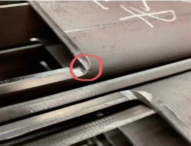
Figure 1 Bending and cracking
The main reasons for bending and cracking are:
- Unclean burrs on the edges of the parts.
- The bending direction is parallel to the rolling direction of the sheet metal.
- The bending radius of the sheet metal is too small.
During the production and manufacturing process, it is necessary to handle bending and cracking phenomena according to specific circumstances. For the bending and cracking problem in Figure 1, the method of adding process holes or process grooves can be adopted to solve it, as shown in Figure 2.
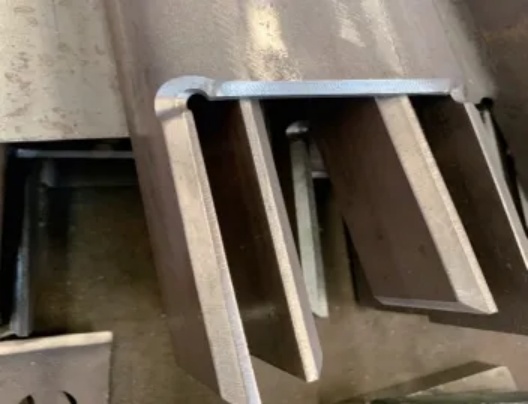
Figure 2: Adding Process Holes
Bending Interference
Bending interference is mainly aimed at products with secondary or higher bending, where the bending edge collides with the mold or equipment, resulting in the inability to form properly. Bending interference is mainly influenced by the shape, size, and mold of the parts, and is mainly caused by the design structure of the bent part itself, the selected bending sequence, and the selected bending mold. Therefore, the main solutions include:
- making new or replacing molds (such as bending knife molds).
- Transforming bending molds (such as mechanical processing of local parts).
- Adjust the bending sequence (such as reverse deformation method).
- Change the bending size of the parts. For example, the installation bracket for the chassis accessory trunking of Shanghai Metro Line 18 is made of U-shaped channel steel, with a medium width of 100mm, edge height of 80mm, and a bending radius of 15mm. Simulate bending based on the existing molds in the workshop to generate bending interference.
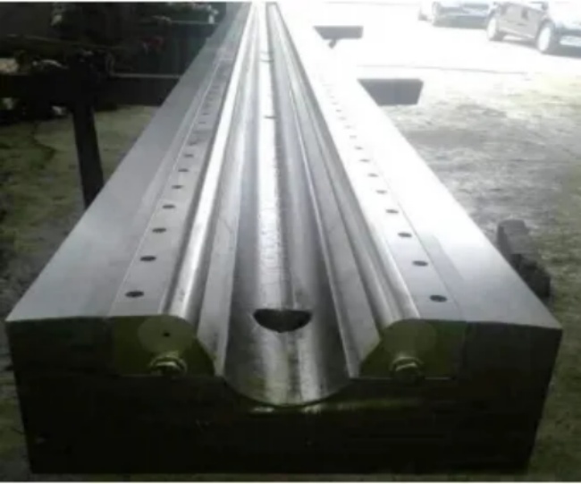
In response to this interference phenomenon, a local mechanical processing method was adopted for the bending upper die (see Figure 3). A 140mm × 48mm notch was cut along the middle line of the existing R15mm straight knife upper die (L=800mm) (see Figure 4). The notch position was determined by combining it with the simulated bending interference position, without affecting its original function. After modifying the bending mold, the problem of bending interference was successfully solved.
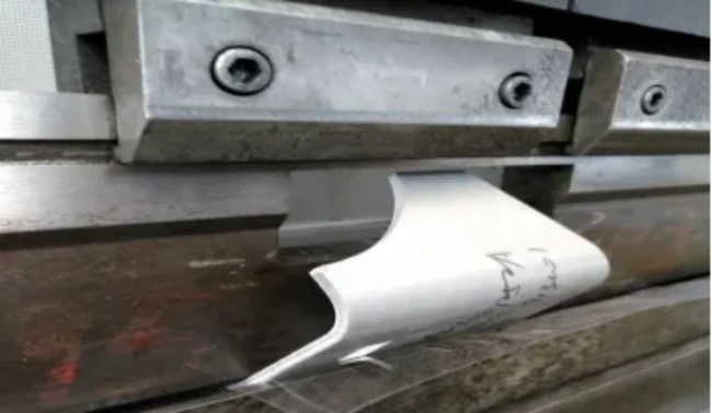
Figure 3: Bending after upper mold processing
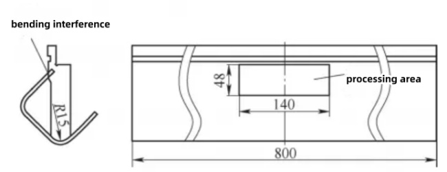
Figure 4: Bending interference, determining the processing area
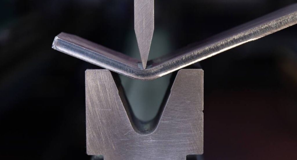
Bending Indentation
Bending indentation is a phenomenon in which friction is generated during the process of gradually bringing the sheet metal into contact with the inner surface of the V-shaped groove of the concave mold, resulting in obvious marks left on the surface of the sheet metal. For some accessories with high surface requirements, traditional bending cannot meet the product quality requirements, and the bending indentation (see Figure 5) cannot meet the requirements of the next process.
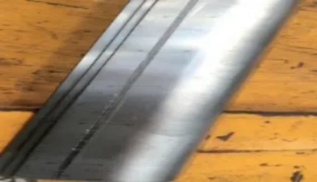
Figure 5: Bending indentation
The bending indentation is mainly affected by the hardness of the sheet metal and the structure of the lower mold. The higher the hardness of the sheet, the greater its ability to resist plastic deformation, making it more difficult for the material to undergo plastic deformation and easier to produce indentation. The probability of bending indentation in commonly used sheet materials is: aluminum > carbon steel > stainless steel. The larger the opening width of the bending die, the larger the width of the bending indentation, and the shallower the indentation depth. The larger the R size of the lower mold opening shoulder, the shallower the indentation depth.
In addition to improving material hardness and lower mold structure, anti indentation rubber pads and ball type bending lower molds can also be used to solve the problem of bending indentation. The anti indentation rubber pad mainly relies on physical isolation to reduce the occurrence of indentation, as shown in Figure 6. The ball type bending die transforms the extrusion friction required for traditional bending molds into rolling friction, reducing friction and minimizing damage to the product, as shown in Figure 7.
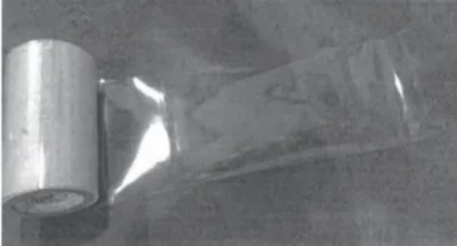
Figure 6: Anti indentation rubber pad
Figure 7: Ball bending lower mold
Bending Springback
During the bending process, materials undergo both plastic deformation and elastic deformation simultaneously. When the workpiece leaves the bending mold, elastic recovery occurs, causing the shape and size of the bent part to be inconsistent with the loading, which is called bending rebound. Bending springback is one of the main reasons for insufficient bending angle. The main factors affecting rebound are the mechanical properties of the sheet metal and the conditions of bending deformation. The magnitude of springback value is directly proportional to the yield strength of the sheet metal and inversely proportional to the elastic modulus. The smaller the relative bending radius (R/t ratio of bending radius to sheet thickness) of the bent part, the smaller the bending springback value. The shape of the bent part also affects the magnitude of the bending springback value. Generally, U-shaped parts have a smaller springback value than V-shaped parts.
The main method to overcome bending springback is the angle compensation method, which generally adopts the method of making a slope equal to the springback angle on the bending mold, which can effectively balance the impact of bending springback. As shown in Figure 8, using a bending mold with a slope of 80°can smoothly bend workpieces with a bending angle of 90°.
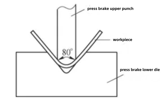
Figure 8: Bending springback compensation
Due to the many factors that affect bending springback, it is very difficult to accurately calculate the springback value. Through trial mold correction and experience accumulation, mastering the springback law, adopting appropriate compensation, and taking measures to overcome springback in mold structure and other aspects are effective methods to ensure product quality.
Bending Slide Material
Bending slide refers to the phenomenon where the workpiece to be bent does not have a complete and effective support point on the lower die groove, resulting in the workpiece being prone to slipping and the bending being unable to be properly positioned.
The main reasons for bending sliding materials are as follows.
- When the width of the lower mold is too large and the bending size is less than half of the width of the lower mold, sliding occurs.
- When the workpiece is affected by its shape and size, and the positioning size of the template is too short or there is no effective template positioning edge, bending and sliding phenomena may occur.
There are two main methods to solve the problem of bending and sliding materials.
- Method 1. Choose a suitable bending die, generally choosing a die width of 4-6 times the thickness of the board for bending.
- Method 2.By using the method of adding templates or process edges, the problem of material slippage caused by poor positioning due to bending can be solved. In general, bending is positioned by a straight edge of the workpiece, which requires two end faces to be in contact with the bending template for positioning. However, in the actual production process, there are situations where the product template edge is too short or there is no effective positioning edge, resulting in the inability to complete bending positioning. The solutions are:
- When the plate thickness t ≤ 6mm, add a process edge for positioning, and the position of the process edge extending should be level with the end edge of the accessory. Laser cutting should be used at the junction to facilitate grinding and elimination after the bending operation is completed.
- When the plate thickness t is greater than 6mm, a template can be cut for positioning, and the template thickness can be equal to or slightly less than the workpiece thickness.Both positioning methods can solve the problem of bending and sliding materials.
Large Arc Bending
During the production and manufacturing process, it is common to encounter situations where the bending radius of the workpiece is large and there is no matching large arc mold in the workshop. In this case, the production cycle of integral forming molds or large arc molds is longer and the cost is too high, while the use of small arc multi pass bending forming technology has lower cost and wider applicability. For example, in the Super Bus 2.0 project, there is a component with one vertical plate and three vertical plates, with a bending radius of 125mm and a bending angle of 90 °, as shown in Figure 9. Due to the lack of corresponding bending molds in the workshop, multiple bending processes can be used. Firstly, a 3D software was used to model the layout and bending at the R125mm position. After modeling, the software automatically unfolded the 2D flat plate diagram. By inputting a 45mm bending radius into the software and comparing multiple data inputs, it was confirmed that the circular arc segment could be guaranteed by bending with 8 cuts. Then, the bending data (bending angle, bending line position length) for each cut was generated, as shown in Figure 10. Finally, on-site trial bending was conducted based on the bending data, as shown in Figure 11.
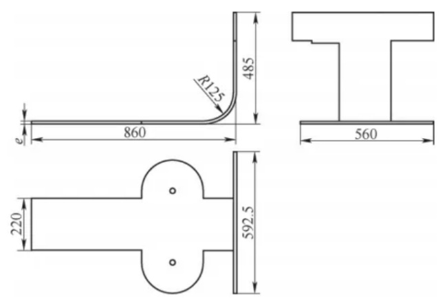
Figure 9: Arc shaped workpieces
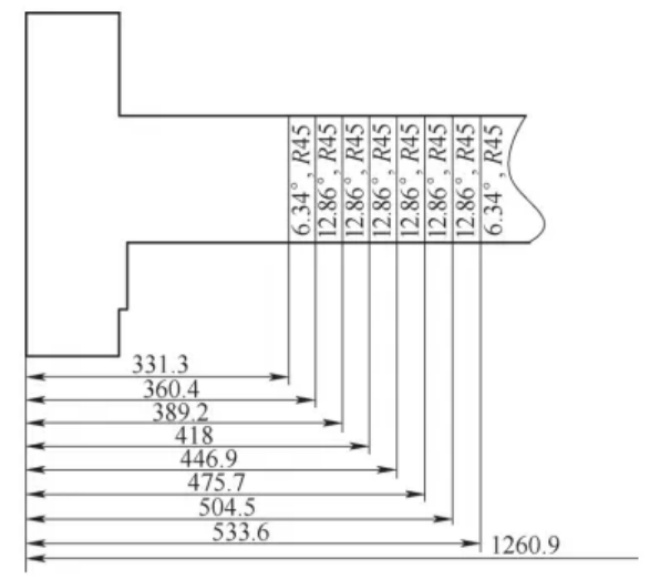
Figure 10: Unfolding diagram and bending line position
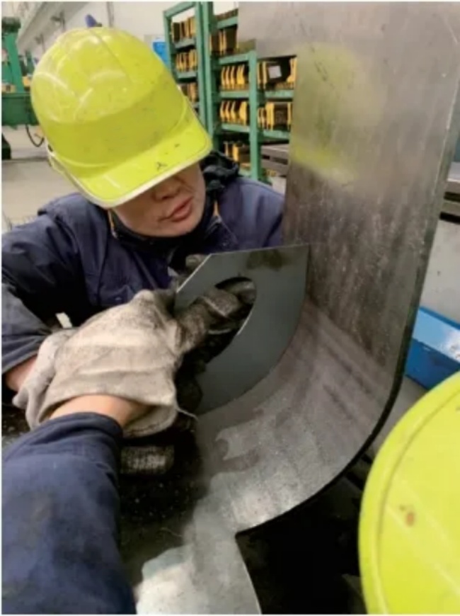
Figure 11: On site trial mold bending
Bending Protrusion
Bending protrusion refers to the phenomenon where the metal material protrudes on both sides of the bent corner of sheet metal due to material compression, resulting in a width larger than the original size. The size of the bending protrusion is generally related to the thickness of the accessory board and the bending radius. The thicker the board, the smaller the bending radius, and the more obvious the protrusion.
To avoid this bending quality problem, process notches can be added on both sides of the bending line during the drawing of the bending unfolding diagram, as shown in Figure 12. The process gap is generally in the form of a circular arc, with a diameter of at least 1.5 times the thickness of the workpiece, in order to offset the bending protrusion and effectively solve the problem of bending protrusion. For workpieces that have already produced bending protrusions, manual polishing is generally used for processing.
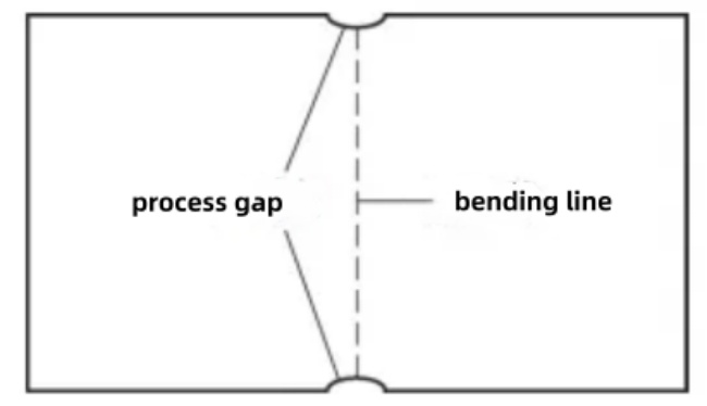
Figure 12: Process Gap
Conclusion
It should be noted that the common bending and cutting quality issues listed above in production practice have not taken into account the impact of human or equipment factors (such as incorrect unfolding dimensions, incorrect bending parameter selection, and equipment aging). In production practice, appropriate bending process parameters should be selected based on equipment performance, product size, and material characteristics, and strictly executed according to operating specifications. We not only need to comprehensively consider the impact of various factors such as project progress, cost, and quality, and adopt appropriate methods to solve bending quality problems, but also need to accumulate experience to predict the occurrence and impact of bending problems in the process analysis stage, and take targeted measures to prevent them. This article lists several common bending quality problems and their solutions, hoping to provide some reference and guidance for industry colleagues.