Table of Contents
Introduction
Calculating the correct K factor, bend allowance, and bend deduction are crucial to getting a good quality finished part from your hydraulic press brake. The knowledge and technique of the press brake are its fundamentals, which are paramount to helping you use it in manufacturing.
Calculating the flat pattern length from the 3D part really is not that difficult. Although you may find several different formulas that claim to calculate the Bend Allowance, they usually are the same formula, only simplified by filling in the angle or a K-factor. This article will show you this information, including the K factor, bend allowance, and bend deduction.
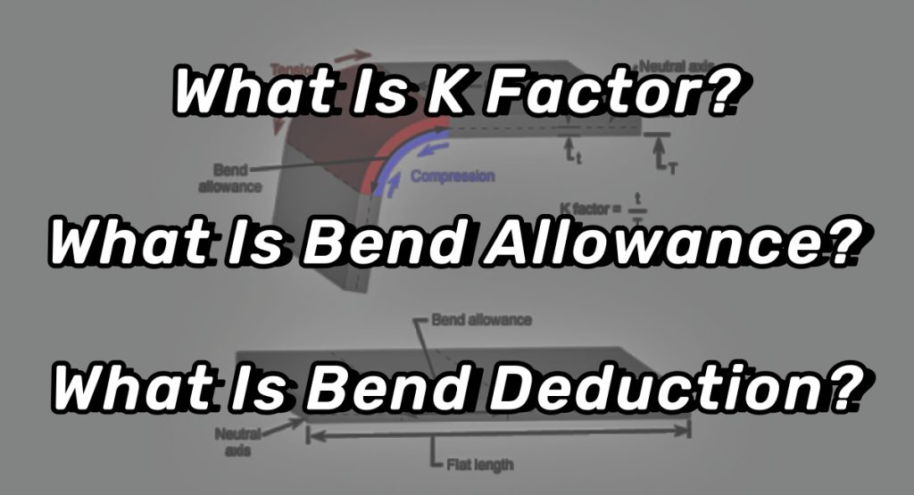
What Is Bend Allowance?
Metals can actually be bent. When manufacturing sheet metal, the metal must be bent, not only to form a certain shape, but also to comply with safety regulations when the metal is subjected to impact, making it bend rather than break. Regardless of the type of metal, as well as the shape and thickness of the metal, each piece of metal has a certain degree of bending allowance.
Bend Allowance Definition
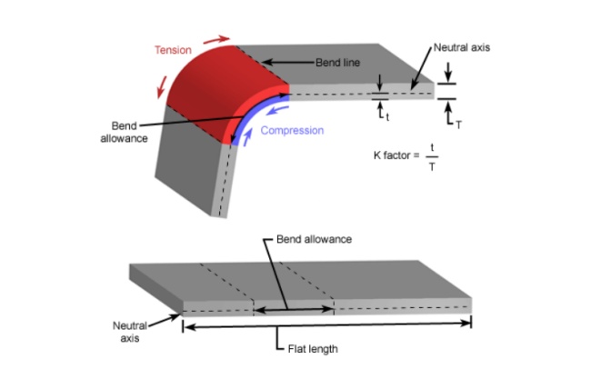
The Bend Allowance (BA) is the arc length of bending measured along the neutral axis of the metal plate since the length of the neutral axis does not change after bending.
Once the bend allowance is calculated, it should be added to the flat length to determine the required sheet metal length needed to form the desired workpiece.
How To Calculate Bend Allowance
As is shown in the below figure:
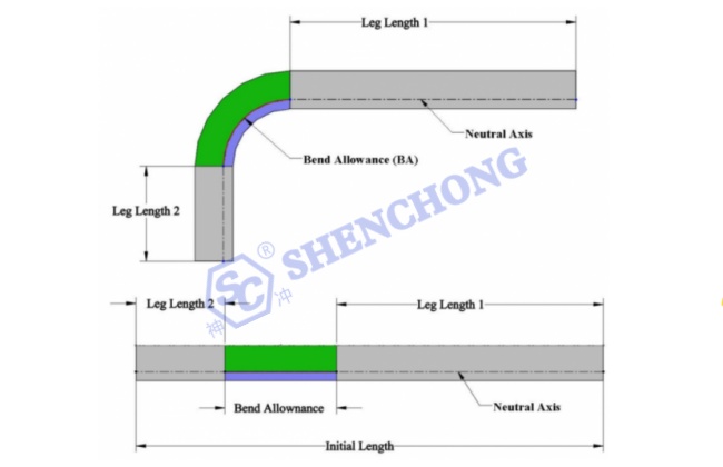
The following formula is used to calculate the flat length:
Sheet Metal Flate Length = Leg Length 1 +BA + Leg Length 2
Bend Allowance Calculation Formula
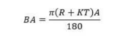
A – Bend angle
R – Inside radius
K – K factor
T – Material thickness
Let’s start with a simple L bracket. The picture shows that the legs of the bracket are 2” and 3”. The material thickness is 0.125”, the inside radius is 0.250”, and the angle of bend is 90 degrees. The flat length is the total of the flat portion of both flanges plus the length through the arc of the bend area. But, do you calculate that on the inside of the material or the outside? Neither! This is where the K-factor comes into play. The K-factor is the percentage of the material thickness where there is no stretching or compressing of the material, for example, the neutral axis. For this simple L bracket, I will use a K-factor of 0.42.
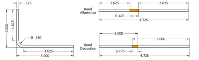
By using the above formula, we have: Bend Allowance = 90 * (π / 180) * (0.250 + 0.42 * 0.125) = 0.475″.
So the flat pattern length is 1.625” + 2.625” + 0.475″ which is equal to 4.725″. So if you add up the flat length of all the flanges and add one Bend Allowance for each bend area you have the correct flat length of the part.
But look at the drawing. That is not how we normally dimension a sheet metal part. The dimensions are usually to the intersection of the flanges or the Mold Line. This means that we have to subtract two times the material thickness plus the bend radius (also known as the Setback) for each bend area. For this set of dimensions, it would be easier to calculate the Bend Compensation value. The Bend Compensation value lets you add up the length of each flange using the Mold Line dimensions and then add one Bend Compensation per bend area to the total. It is -0.275, a negative number, which means you will subtract this amount from the total of the flange lengths, 5”, to get 4.725″.
What Is K Factor?
The k-factor is the percentage of the material thickness where there is no stretching or compressing of the material in the bend area.
The harder the material, the less compression there is on the inside of the bend. Therefore, more stretching on the outside and the neutral axis moves toward the inside of the bend. Softer materials allow more compression on the inside and the neutral axis remains closer to the center of the material thickness.
Bend radius has a similar effect. The smaller the bend radius, the more need for compression and the neutral axis moves toward the inside of the bend. On a larger radius. the neutral axis remains near the center of the material thickness.
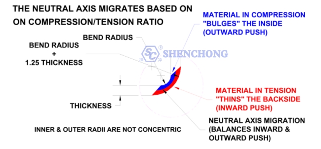
To understand K factor, we need to firstly understand the neutral axis.
When sheet metal is bent, the bottom surface is compressed, and the top surface is stretched. The neutral axis is located inside the metal where it will neither be compressed nor expanded, allowing it to maintain a constant length.
Neutral Axis
The Neutral Axis does not change.When developing a flat blank length, there is a length of the part that does not changeThis length is called the neutral axis. Material on the inside of the neutral axis wilcompress, while material on the outside will stretch. Based on the material thicknessform radius and forming methods, the ratio of compression to tension in the part wilchange.
A part that is bent over a very sharp radius, when compared to the thickness, willstretch more on the outside, which means that the neutral axis will lie closer to theinside of the bend. A part that is gradually bent will have less outside stretch, whichmeans that the neutral axis will lie closer to the center of the part.
In flat sheet metal, the neutral axis is evenly located at half the thickness of the sheet metal, but it will move during bending.
The position change of the neutral axis is determined by various factors such as the material properties, thickness, bending angle, internal radius, and bending method of the plate.
How To Calculate K Factors
Mathematically, the K-factor represents the ratio between the position of the neutral axis (t) and the plate thickness (T).
K Factors Formula

Where t is the distance from the inside surface to the neutral axis and T is the metal thickness.
The K-factor is determined by the physical properties of the material, bending method, bending angle, and other factors.
The value of K factors will always be between 0 and 1. If a k factor is 0.25, it means that the neutral axis is located at 25% of the thickness of the sheet metal material of the part. Similarly, if it is 0.5, it means that the neutral axis is located at 50% of the entire thickness.
Material Properties: it typically ranges between 0.30 and 0.50. In general, the K-factor of soft copper or soft copper materials is 0.35, the K-factor of materials such as semi-hard copper or brass, mild steel and aluminium is 0.41, and the K-factor of materials such as bronze, hard copper, cold-rolled steel and spring steel is 0.45.
Bending radius: the smaller the bending radius, the greater the K-factor.
Material thickness: the greater the material thickness, the greater the K-factor.
Material’s yield strength: the higher the yield strength, the smaller the K-factor.
Elastic modulus (also known as Young’s modulus): the greater the material thickness, the greater the K-factor.
In precision sheet metal manufacturing by using CNC press brake, the K-factor is a crucial factor. The K-factor is used to calculate the bending flat pattern, which is directly related to the length of the sheet metal stretched during bending.
It is the fundamental value for determining the bending allowance and bending deduction.
Since the ratio of the distance to the neutral axis to the plate thickness determines the position of the neutral axis in the metal plate, knowing the K-factor helps determine the position of the neutral axis after bending.
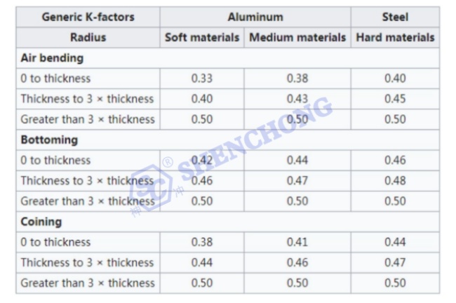
K Factors For Aluminum And Steel
You can also determine the K-factor using the table below:
K Factors For Copper, Brass And Bronze
After careful study, it was found that the SolidWorks system also provides bending compensation algorithms for the following specific materials at a bending angle of 90 degrees. The specific calculation formula is as follows:
Soft brass or soft copper material: BA=(0.55 * T)+(1.57 * R)
Materials such as semi hard copper or brass, soft steel, and aluminum: BA=(0.64 * T)+(1.57 * R) Materials such as bronze, hard copper, cold-rolled steel, and spring steel: BA=(0.71 * T)+(1.57 * R) Actually, if we simplify equation (7) and set the bending angle to 90 degrees and calculate the constant, the equation can be transformed into:
BA=(1.57 * K * T)+(1.57 * R)
So, for soft brass or soft copper materials, by comparing the above calculation formula, we can obtain 1.57xK=0.55K=0.55/1.57=0.35. It is easy to calculate the k-factor values of several types of materials listed in the book using the same method.
Soft brass or soft copper material: K=0.35.
Materials such as semi hard copper or brass, soft steel, and aluminum: K=0.41.
Materials such as bronze, hard copper, cold-rolled steel, and spring steel: K=0.45.
What Is Bend Deduction?
When bending sheet metal, due to incomplete plastic deformation of the material and structural limitations of the machine tool itself, the angle and length of the bent workpiece may deviate from the designed dimensions. In order to ensure the accuracy of bending and the size of the workpiece meets the requirements, it is necessary to consider bending deduction during the production of the drawing, that is, to reduce the size of the bending that needs to be done.
Bend Deduction Definition
Bend deduction is the length of material that we need to remove from the total length of the plate to obtain the correct flat pattern.
Bend Deduction Principle
The principle of bending deduction is to utilize the elastic deformation of the material, so that the length and angle after bending can meet the design requirements. When bending, the sheet metal is placed on the bending machine, which applies bending force to cause elastic deformation of the sheet metal, resulting in changes in shape and angle, and ultimately becoming the desired shape. In this process, the bending deduction can be precisely controlled by adjusting the size of the drawing, achieving the precision and size required by the design.
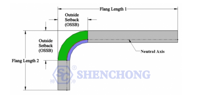
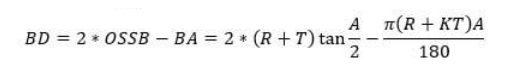
According to the figure above, the bend deduction is the difference between the bend allowance and twice the outside setback.
Bend Deduction Calculation Formula
Where:
OSSB – The outside setback (the length of the part that extends beyond the bend angle).
R – Bend radius
K – K-factor (determined by material properties and thickness)
T – Material thickness
A – Desired bend angle in degrees
Let’s assume we want to bend a 2mm thick stainless steel sheet to a 90° angle with an inside bend radius of 3mm. The K-factor for this material is known to be 0.44. Let’s calculate the Bend Deduction step by step:
- Calculate the Bend Allowance (BA):
BA = π * (R + K * T) * (A / 180)
Where R is the inside bend radius, K is the K-factor, T is the sheet thickness, and A is the bend angle.
Plugging in the values:
BA = π * (3 + 0.44 * 2) * (90 / 180) = 4.39mm
- Calculate the Outside Setback (OSSB):
OSSB = R + T = 3 + 2 = 5mm
- Calculate the Bend Deduction (BD):
BD = 2 * OSSB – BA
Plugging in the values:
BD = 2 * 5 – 4.39 = 5.61mm
Therefore, to achieve a 90° bend with a 3mm inside bend radius on this 2mm thick stainless steel sheet, we need to set the Bend Deduction to 5.61mm during the bending process.
This means we need to over-bend the sheet by 5.61mm to compensate for the springback after bending, ultimately achieving the desired 90° bend angle.
The calculation of the bend deduction can help determine the part dimensions before bending, allowing for better production planning and reduced material waste.
Main Functions Of Bending Deduction
- Ensure bending accuracy. Bending deduction can control the length and angle of the bent sheet metal, thereby ensuring that the produced sheet metal parts meet the size and accuracy requirements of the design.
- Improve processing efficiency. The design of bending deduction not only reduces the production size, but also avoids repeated experiments and adjustments, thereby improving the efficiency of making sheet metal parts.
- Reduce material waste. By using bending deduction to control dimensions, excessive processing or material waste can be avoided, thereby reducing costs and improving production efficiency.
In short, bending deduction is a very important link in the sheet metal processing process, and it is also the key to ensuring the quality and accuracy of the finished product. In actual processing, the bending deduction value should be adjusted reasonably according to the specific situation to achieve the best processing effect.
Materials With Different Bend Allowance
What Metal Can Bend Well?
All metals have a certain degree of elasticity. Some metals are more elastic than others and may achieve greater bending allowances compared to other materials. Metals are ranked according to their elastic modulus, which is the ratio between stress and strain in metal deformation. Elastic modulus is also a means of measuring material stiffness or elastic resistance. Other materials such as rubber and glass can also be calculated in the same way.
Surprisingly, one of the most elastic metals is nickel titanium, also known as nickel titanium, with a pressure of 28 GPa. It can be tightened many times to a large extent without being considered deformed. Among common metal types, the second largest elastic metals include 45 GPa of tin, magnesium, cadmium, and 69 GPa of aluminum. Of course, aluminum is known for its lightweight and bending ability, but in terms of pure metals, including alloys, there are some metals that can surpass it in this regard.
Which Metals Cannot Bend Well, Or Will Fracture When Bent Too Far?
As is well known, most metals are very hard, and if the material is not bent, it will definitely fracture when bent. Among all alloys, tungsten is the hardest metal, reaching up to 411 GPa. Even in its thinnest form, tungsten is difficult to bend, so it is likely to break like glass. The second hardest metal is 304GPa beryllium copper. Chromium is a material found in diamonds and other gemstones, ranking third with 279 GPa. Wrought iron and cobalt both have 211 GPa. At 210GPa, you have many more common metal sheets, such as steel, stainless steel, cobalt, and nickel. As you know, most metals are considered very hard, but as mentioned earlier, some metals are not as hard as others.
Conclusion
The K-factor, also known as the bend radius factor, accounts for the material’s tendency to stretch on the outer surface and compress on the inner surface during bending.
Proper calculation of the K-factor is important for determining the neutral axis position and minimizing potential defects like cracking or wrinkling.
Bend allowance refers to the additional material required to accommodate the bend radius, preventing excessive stretching or compression of the material.
Accurate calculation of bend allowance is vital for ensuring the final part dimensions align with the design specifications.
Bend deduction, on the other hand, compensates for the material’s spring back effect, where the bent part tends to partially unbend after the bending force is removed.
Accounting for bend deduction is essential to achieve the desired bend angle and maintain dimensional accuracy.
By understanding and properly applying these essential factors, you can optimize their bending processes, minimize material waste, and consistently produce high-quality bent components that meet the most stringent requirements.