Table of Contents
General Introduction
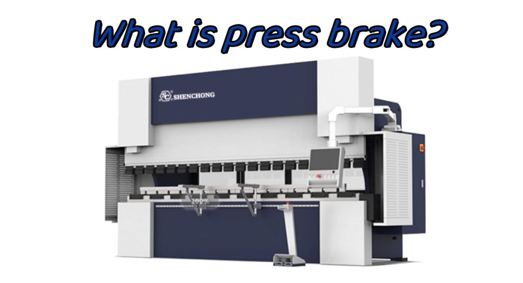
What is press brake? A press brake is a machine that can bend thin plates. Its structure mainly includes a bracket, a workbench, and a clamping plate. The workbench is placed on the bracket, and the workbench is composed of a base and a pressure plate. The base is connected to the clamping plate through hinges, and the base is composed of a seat shell, a coil, and a cover plate. The coil is placed in the depression of the seat shell, and the top of the depression is covered with a cover plate. When in use, the coil is energized by a wire, which generates a gravitational force on the pressure plate, thereby achieving the clamping of the thin plate between the pressure plate and the base. Due to the use of electromagnetic force clamping, the pressure plate can be made into various workpiece requirements, and can be processed on workpieces with side walls, making the operation very simple.
What is Press Brake Working Principle
The hydraulic press brake machine includes a bracket, a workbench, and a clamping plate. The workbench is placed on the bracket, and the workbench is composed of a base and a pressure plate. The base is connected to the clamping plate through hinges, and the base is composed of a seat shell, a coil, and a cover plate. The coil is placed in the depression of the seat shell, and the top of the depression is covered with a cover plate.
When in use, the coil is energized by a wire, which generates a gravitational force on the pressure plate, thereby achieving the clamping of the thin plate between the pressure plate and the base. Due to the use of electromagnetic force clamping, the pressure plate can be made into various workpiece requirements, and can be used to process workpieces with side walls. The press brake can meet the needs of various workpieces by replacing the press brake tooling.
Press Brake Categories
Press brake machines are divided into manual bending machines, hydraulic press brake machines, and servo hybrid press brake machines. Manual bending machines are further divided into mechanical manual bending machines and electric manual bending brakes. Hydraulic bending brake machines can be divided into torsion axis synchronization, hydraulic synchronization, and electro-hydraulic synchronization according to the synchronization method. Hydraulic bending brake machines can be divided into upward and downward movement types according to their movement modes.
Mechanical bending machines are usually have very small bending capacity and low bending accuracy. If you need to use small tonnage bending brake, we have high speed mini press brake for sale, which is hydraulic bending machine with CNC controller.
What is Hydraulic Press Brake
The hydraulic control system of the hydraulic press brake machine is the central brain of the bending machine itself, and high automation and standardization rates are required in the production of the bending machine. Therefore, hydraulic systems are also limited to hydraulic control methods, and the different structural types and principles of these methods have been widely recognized in the market.
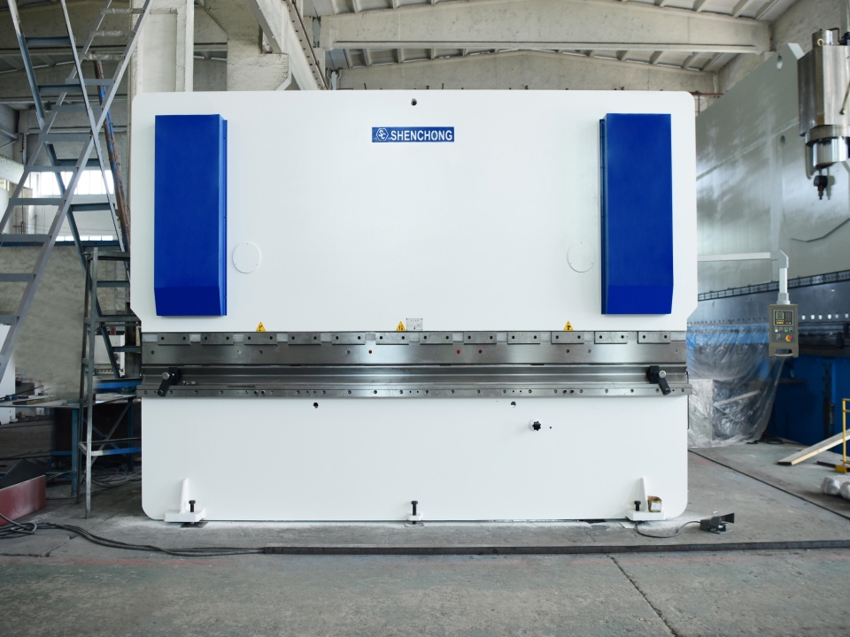
Structural Description
- Sliding block part: Hydraulic transmission is adopted, and the sliding block part is composed of a sliding block, an oil cylinder, and a mechanical stopper fine-tuning structure. The left and right oil cylinders are fixed on the frame, and the piston (rod) is driven by hydraulic pressure to move the slider up and down. The mechanical stopper is controlled and adjusted by the numerical control system.
- Workbench section: Operated by a button box, the electric motor drives the material blocking frame to move forward and backward, and the distance of movement is controlled by the CNC system, with a minimum reading of 0.01 millimeters (both front and rear positions have travel switch limits).
- Synchronous system: This machine is a mechanical synchronization mechanism composed of a torsion shaft, swing arm, joint bearings, etc., with a simple structure, stable and reliable performance, and high synchronization accuracy. The mechanical stopper is adjusted by the motor and the numerical control system controls the value.
- Material blocking mechanism: The material blocking is driven by an electric motor, which drives the two screw rods to move synchronously through chain operation. The CNC system controls the size of the material blocking.
Structural Characteristics
- Adopting an all steel welded structure with sufficient strength and rigidity.
- Hydraulic transmission, the oil cylinders at both ends of the machine tool are placed on the sliding block, directly driving the sliding work.
- The slider synchronization mechanism adopts forced synchronization with a torsion axis.
- Adopting a mechanical block structure, stable and reliable.
- Mobile quick adjustment of slider stroke, manual fine adjustment, counter display.
- The inclined wedge type deflection compensation mechanism ensures high bending accuracy.
Usage
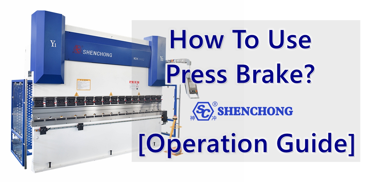
Processing with ordinary hydraulic press brake machines
A brief introduction to Q235 sheet metal:
- Firstly, turn on the power, turn on the key switch on the control panel, and then press the oil pump to start.
- Travel adjustment: When using the bending machine, attention must be paid to adjusting the travel, and a test run must be conducted before bending. When the upper mold of the bending machine descends to the bottom, there must be a gap of plate thickness. Otherwise, it will cause damage to the mold and machine. The adjustment of the stroke also includes electric quick adjustment and manual fine adjustment.
- The selection of bending groove generally requires selecting a groove 8 times the width of the plate thickness. If bending a 4mm sheet metal, a groove of around 32 needs to be selected.
- The adjustment of the rear stopper generally includes electric quick adjustment and manual fine adjustment, using the same method as the shearing machine.
- Press the foot switch to start bending. The press brakeis different from the shearing machine and can be released at any time. Release the foot switch and the bending machine will stop, then press it again to continue down.
With CNC Controller Or Not
Hydraulic press brake can be designed as CNC press brake that controlled by CNC controller, NC press brake that controlled by NC controller, or normal hydraulic press brake without any controller.
To bend large plate sheet, it is best to choose CNC hydraulic press brake to connect together as the heavy duty tandem press brake for its stable quality.
What is Hybrid Servo Press Brake
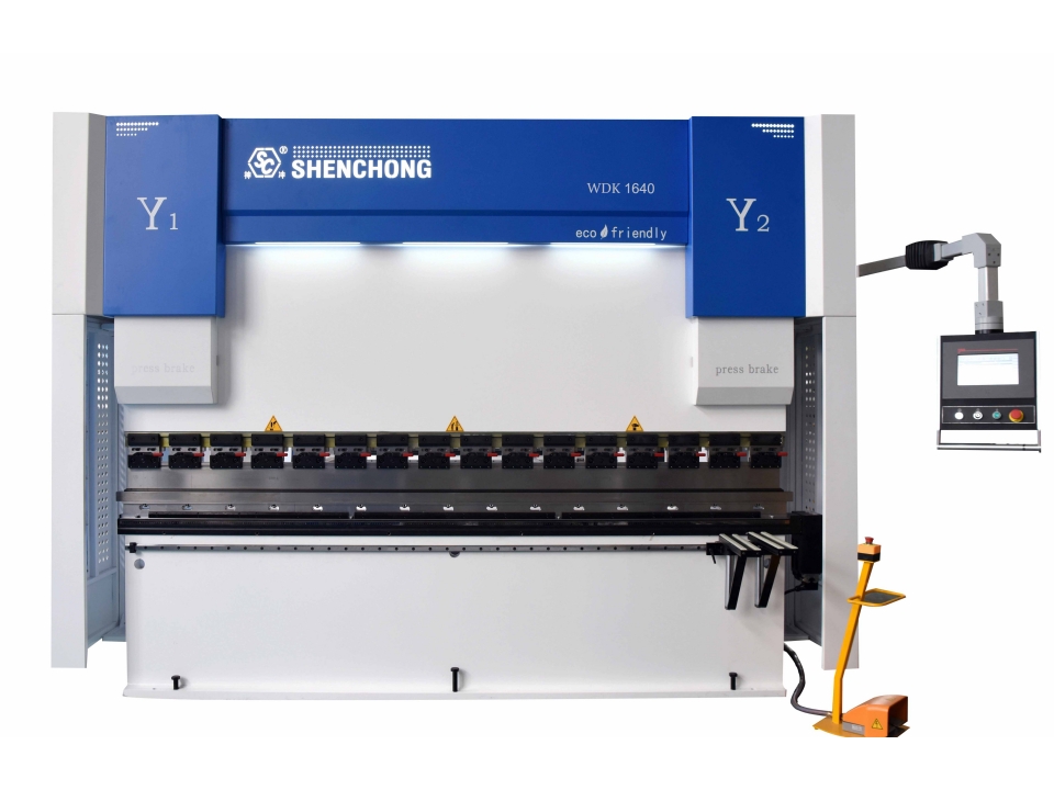
Oil electric hybrid press brake is a new type of mechanical equipment that combines traditional mechanical bending technology, electronic technology, and hydraulic system.
Its advantage lies in its ability to provide high-speed and high-precision bending operations, significantly improving processing efficiency and product consistency. In addition, the design of the oil electric hybrid press brake machine also takes into account the needs of energy conservation and noise reduction, and achieves these goals by effectively combining electrical and hydraulic energy. The servo motor is one of the power sources of the bending machine, and the hydraulic system is responsible for providing the required torque for bending. The electrical system controls the angle and speed of bending to ensure accuracy and smoothness of operation.
Working Principle
The oil electric hybrid CNC (pump controlled) bending machine includes a power unit connected to the CNC system and a control valve group. The power unit includes a servo motor and a one-way quantitative pump connected to the servo motor, as well as an independent fuel tank; The control valve group includes relief valve, unloading valve, one-way valve, directional valve, backpressure valve, lifting valve, safety valve, and filling valve.
By controlling the speed of the servo motor of the power unit through a CNC system, the displacement of the oil pump connected to it is controlled, thereby achieving displacement speed control of the actuator (oil cylinder). By setting the torque of the servo motor through the CNC system, control the output force of the left and right execution components (cylinders).
By using displacement sensors (grating rulers or magnetic grating rulers), the displacement readings of the left and right execution components (cylinders) are fed back to the CNC system. After comparison, the CNC system controls the left and right power units, thereby achieving closed-loop control of synchronization and positioning of the left and right execution components (cylinders). The displacement sensor forms an internal feedback loop to improve the control accuracy of the system.
Hydraulic Control Press Brake (Valve Control) VS. Hybrid Servo Control Press Brake (Pump Control)
- Efficient: The equipment runs at 90% load for 2 hours, increasing efficiency by 30% to 50%.
- Energy saving: The device operates at 90% load for 2 hours, increasing energy efficiency by 28% to 54%.
- Accuracy: The equipment runs at 90% load in 2 hours, with small Y-axis walking error and an average increase of 5 times in accuracy at any position.
- Low noise: The device operates at 90% load for 2 hours, reducing noise by 10-12 dB and greatly optimizing the working environment.
- Environmental protection: The equipment operates at 90% load for 2 hours, reducing hydraulic oil volume by 50% to 80%.
- Temperature control: The equipment operates at 90% load for 2 hours, with superior oil temperature control, which is conducive to the operation of the entire machine.
